Google Search Page

Google

Thursday, February 14, 2008

INTERFACES

Intro to I/O :
There are four I/O buses in the modern PC architecture and each of them has several functions. They may lead to internal and external ports or they lead to other controlling buses. The four buses are:
· ISA, which is old, slow, and limited, compared to the alternatives listed below. We hope that it is replaced by the following interfaces:
· PCI, which is the newer high speed multifunction I/O bus.
· AGP, which only is used for graphics adapter.
· USB, which is the new low speed I/O bus to replace ISA.
The ISA and the PCI bus both end up having to exits:
· Internal I/O ports (LPT, KBD, COM1, COM2, EIDE etc.).
. Expansion slots in the system board, in which we can insert adapters.
If you look at this illustration you will see the overview of this architecture:

If we focus on the right end of the illustration we approach the I/O units. Here you get a closer look at that:


As you see, there is room for a lot of units to be connected to the PC.
The PCI bus is the most loaded of all the buses. It is used for so many purposes that the output for the graphics adapter has been isolated on its own AGP-bus.
But still the PCI bus is heavyly loaded, connecting the system bus to the network controller and the various EIDE- and SCSI drives. Because of the high bandwidth of the FireWire bus, overall throughput of both interfaces would be improved by separating these. We hope to see a separate FireWire interface in future motherboard architectures.

Wednesday, February 13, 2008

FILE SYSTEMS

The precise manner in which data is organised on a hard disk drive is determined by the file system used. File systems are generally operating system dependent. However, since it is the most widely used PC operating system, most other operating systems' file systems are at least read-compatible with Microsoft Windows.
The FAT file system was first introduced in the days of MS-DOS way back in 1981. The purpose of the File Allocation Table is to provide the mapping between clusters - the basic unit of logical storage on a disk at the operating system level - and the physical location of data in terms of cylinders, tracks and sectors - the form of addressing used by the drive's hardware controller.The FAT file system was first introduced in the days of MS-DOS way back in 1981. The purpose of the File Allocation Table is to provide the mapping between clusters - the basic unit of logical storage on a disk at the operating system level - and the physical location of data in terms of cylinders, tracks and sectors - the form of addressing used by the drive's hardware controller.
The FAT contains an entry for every file stored on the volume that contains the address of the file's starting cluster. Each cluster contains a pointer to the next cluster in the file, or an end-of-file indicator at (0xFFFF), which indicates that this cluster is the end of the file. The diagram shows three files: File1.txt uses three clusters, File2.txt is a fragmented file that requires three clusters and File3.txt fits in one cluster. In each case, the file allocation table entry points to the first cluster of the file.

The first incarnation of FAT was known as FAT12, which supported a maximum partition size of 8MB. This was superseded in 1984 by FAT16, which increased the maximum partition size to 2GB. FAT16 has undergone a number of minor modifications over the years, for example, enabling it to handle file names longer than the original limitation of 8.3 characters. FAT16's principal limitation is that it imposes a fixed maximum number of clusters per partition, meaning that the bigger the hard disk, the bigger the cluster size and the more unusable space on the drive. The biggest advantage of FAT16 is that it is compatible across a wide variety of operating systems, including Windows 95/98/Me, OS/2, Linux and some versions of UNIX.

Dating from the Windows 95 OEM Service Release 2 (OSR2), Windows has supported both FAT16 and FAT32. The latter is little more than an extension of the original FAT16 file system that provides for a much larger number of clusters per partition. As such, it offers greatly improved disk utilisation over FAT16. However, FAT32 shares all of the other limitations of FAT16 plus the additional one that many non-Windows operating systems that are FAT16-compatible will not work with FAT32. This makes FAT32 inappropriate for dual-boot environments, although while other operating systems such as Windows NT can't directly read a FAT32 partition, they can read it across the network. It's no problem, therefore, to share information stored on a FAT32 partition with other computers on a network that are running older versions of Windows.

With the advent of Windows XP in October 2001, support was extended to include the NTFS. NTFS is a completely different file system from FAT that was introduced with first version of Windows NT in 1993. Designed to address many of FAT's deficiencies, it provides for greatly increased privacy and security. The Home edition of Windows XP allows users to keep their information private to themselves, while the Professional version supports access control and encryption of individual files and folders. The file system is inherently more resilient than FAT, being less likely to suffer damage in the event of a system crash and it being more likely that any damage is recoverable via the chkdsk.exe utility. NTFS also journalises all file changes, so as to allow the system to be rolled back to an earlier, working state in the event of some catastrophic problem rendering the system inoperable.

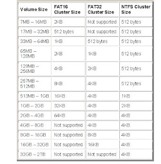
FAT16, FAT32 and NTFS each use different cluster sizes depending on the size of the volume, and each file system has a maximum number of clusters it can support. The smaller the cluster size, the more efficiently a disk stores information because unused space within a cluster cannot be used by other files; the more clusters supported, the larger the volumes or partitions that can be created.


Tuesday, February 12, 2008

HARD DISK - STUDY NOTES

When the power to a PC is switched off, the contents of memory are lost. It is the PC's hard disk that serves as a non-volatile, bulk storage medium and as the repository for a user's documents, files and applications. It's astonishing to recall that back in 1954, when IBM first invented the hard disk, capacity was a mere 5MB stored across fifty 24in platters. 25 years later Seagate Technology introduced the first hard disk drive for personal computers, boasting a capacity of up to 40MB and data transfer rate of 625 KBps using the MFM encoding method. A later version of the company's ST506 interface increased both capacity and speed and switched to the RLL encoding method. It's equally hard to believe that as recently as the late 1980s 100MB of hard disk space was considered generous. Today, this would be totally inadequate, hardly enough to install the operating system alone, let alone a huge application such as Microsoft Office.

There's a read/write head for each side of each platter, mounted on arms which can move them towards the central spindle or towards the edge. The arms are moved by the head actuator, which contains a voice-coil - an electromagnetic coil that can move a magnet very rapidly. Loudspeaker cones are vibrated using a similar mechanism.

The PC's upgradeability has led software companies to believe that it doesn't matter how large their applications are. As a result, the average size of the hard disk rose from 100MB to 1.2GB in just a few years and by the start of the new millennium a typical desktop hard drive stored 18GB across three 3.5in platters. Thankfully, as capacity has gone up prices have come down, improved areal density levels being the dominant reason for the reduction in price per megabyte.

Construction:

Hard disks are rigid platters, composed of a substrate and a magnetic medium. The substrate - the platter's base material - must be non-magnetic and capable of being machined to a smooth finish. It is made either of aluminium alloy or a mixture of glass and ceramic. To allow data storage, both sides of each platter are coated with a magnetic medium - formerly magnetic oxide, but now, almost exclusively, a layer of metal called a thin-film medium. This stores data in magnetic patterns, with each platter capable of storing a billion or so bits per square inch (bpsi) of platter surface.


Platters vary in size and hard disk drives come in two form factors, 5.25in or 3.5in. The trend is towards glass technology since this has the better heat resistance properties and allows platters to be made thinner than aluminium ones. The inside of a hard disk drive must be kept as dust-free as the factory where it was built. To eliminate internal contamination, air pressure is equalised via special filters and the platters are hermetically sealed in a case with the interior kept in a partial vacuum. This sealed chamber is often referred to as the head disk assembly (HDA).
Typically two or three or more platters are stacked on top of each other with a common spindle that turns the whole assembly at several thousand revolutions per minute. There's a gap between the platters, making room for magnetic read/write head, mounted on the end of an actuator arm. This is so close to the platters that it's only the rush of air pulled round by the rotation of the platters that keeps the head away from the surface of the disk - it flies a fraction of a millimetre above the disk. On early hard disk drives this distance was around 0.2mm. In modern-day drives this has been reduced to 0.07mm or less. A small particle of dirt could cause a head to "crash", touching the disk and scraping off the magnetic coating. On IDE and SCSI drives the disk controller is part of the drive itself.

There's a read/write head for each side of each platter, mounted on arms which can move them towards the central spindle or towards the edge. The arms are moved by the head actuator, which contains a voice-coil - an electromagnetic coil that can move a magnet very rapidly. Loudspeaker cones are vibrated using a similar mechanism.
The heads are designed to touch the platters when the disk stops spinning - that is, when the drive is powered off. During the spin-down period, the airflow diminishes until it stops completely, when the head lands gently on the platter surface - to a dedicated spot called the landing zone (LZ). The LZ is dedicated to providing a parking spot for the read/write heads, and never contains data.
When a disk undergoes a low-level format, it is divided it into tracks and sectors. The tracks are concentric circles around the central spindle on either side of each platter. Tracks physically above each other on the platters are grouped together into cylinders which are then further subdivided into sectors of 512 bytes apiece. The concept of cylinders is important, since cross-platter information in the same cylinder can be accessed without having to move the heads. The sector is a disk's smallest accessible unit. Drives use a technique called zoned-bit recording in which tracks on the outside of the disk contain more sectors than those on the inside.
Operation
Data is recorded onto the magnetic surface of the disk in exactly the same way as it is on floppies or digital tapes. Essentially, the surface is treated as an array of dot positions, with each "domain' of magnetic polarisation being set to a binary "1" or "0". The position of each array element is not identifiable in an "absolute" sense, and so a scheme of guidance marks helps the read/write head find positions on the disk. The need for these guidance markings explains why disks must be formatted before they can be used.
When it comes to accessing data already stored, the disk spins round very fast so that any part of its circumference can be quickly identified. The drive translates a read request from the computer into reality. There was a time when the cylinder/head/sector location that the computer worked out really was the data's location, but today's drives are more complicated than the BIOS can handle, and they translate BIOS requests by using their own mapping.

In the past it was also the case that a disk's controller did not have sufficient processing capacity to be able to read physically adjacent sectors quickly enough, thus requiring that the platter complete another full revolution before the next logical sector could be read. To combat this problem, older drives would stagger the way in which sectors were physically arranged, so as to reduce this waiting time. With an interleave factor of 3, for instance, two sectors would be skipped after each sector read. An interleave factor was expressed as a ratio, "N:1", where "N" represented the distance between one logical sector and the next. The speed of a modern hard disk drive with an integrated controller and its own data buffer renders the technique obsolete

Processor - study notes


what is the processor? Well in the simplest of terms, it’s your computers brain. The processor tells your computer what to do and when to do it, it decides which tasks are more important and prioritizes them to your computers needs.


There is and has been many processors on the market, running at many different speeds. The speed is measured in Megahertz or MHz. A single MHz is a calculation of 1 million cycles per second (or computer instructions), so if you have a processor running at 2000 MHz, then your computer is running at 2000,000,000 cycles per second, which in more basic terms is the amount of instructions your computer can carry out. Another important abbreviation is Gigahertz or GHz. A single GHz or 1 GHz is the same as 1000 MHz . Sounds a bit confusing, so here is a simple conversion :
1000 MHz (Megahertz) = 1GHz (Gigahertz) = 1000,000,000 Cycles per second (or computer instructions).


when buying a new computer always look for fastest you can afford. The fastest on the market at the time of writing this article is 3.8 GHz (3800 MHz). Remember though that it is not necessary to purchase such a fast processor, balance your needs, do you really need top of the range? Especially when the difference say between a 3.5 GHz (3500 MHz) and a 3.8 GHz (3800 MHz) processor will be barely noticed (if noticed at all) by you, while the price difference is around £100. With the money you save you could get a nice printer and scanner package.
Now that we have covered the speeds, there is one more important subject to cover. Which processor? There are 3 competitors at present, the AMD Athlon, Intel Pentium and the Intel Celeron.


The Intel Pentium 4 is the most expensive of them all, and remains today the most popular on the market. In layman’s terms it’s the designer processor, although AMD have some superb if not better releases


The AMD Athlon 64 and 64 X2 processors are a direct competitor to the Pentium 4, the decision of which to pick should be left to your budget and present reviews, check out magazines and online hardware sites.
One thing to note though is that AMD lists its processor speeds at what it calls a comparable rating to the Intel Pentium 4. An example of this would be the 2200+ Athlon XP processor, which actually only runs at 1.8 GHz (1800 MHz).


Lastly there is the Intel Celeron; this processor is a budget version of the Intel Pentium 4, the processor you find in most budget computers. If the purse is tight, and you need a computer, then this is your port of call.

Monday, February 11, 2008

Non-Parity vs. Parity

Parity
As data moves through your computer (e.g. from the CPU to the main Memory), the possibility of errors can occur . . . particularly in older 386 & 486 machines. Parity error detection was developed to notify the user of any data errors. By adding a single bit to each byte of data, this bit is responsible for checking the integrity of the other 8 bits while the byte is moved or stored. Once a single-bit error is detected, the user receives an error notification; however, parity checking only notifies, and does not correct a failed data bit. If your SIMM module has 3, 6, 9, 12, 18, or 36 chips then it is more than likely Parity.

Logic Parity
Also known as Parity Generators, or Fake Parity, these modules were produced by some
manufacturers as a less expensive alternative to True Parity. Fake parity modules "fool" your
system into thinking parity checking is being done. This is accomplished by sending the parity signal the machine looks for, rather than using an actual parity bit. In a module using Fake Parity, you will NOT be notified of a Memory error, because it is really not being checked. The result of these undetected errors can be corrupted files, wrong calculations, and even corruption of your hard disk. If you need Parity modules be cautious of suppliers with bargain prices; they may be substituting useless Fake Parity.
Non-Parity
These modules are just like Parity modules without the extra chips. There are no Parity chips in
Apple® Computers, later 486, and most Pentium® class systems. The reason for this is simply
because Memory errors are rare, and a single bit error will most likely be harmless.If your SIMM module has 2, 4, 8, 16, or 32 chips, then it is more than likely Non-Parity. Always match the new Memory with what is already in your system. To determine if your system requires parity, count the number of small, black, IC chips on one of your modules.

ECC (Error Correction Code)
Error Correction Code modules are an advanced form of Parity detection often used in servers and critical data applications. ECC modules use multiple Parity bits per byte (usually 3) to detect doublebit errors. They also will correct single-bit errors without creating an error message. Some systems which support ECC can use a regular Parity module by using the Parity bits to make up the ECC code. However, a Parity system cannot use a true ECC module.

FPM (Fast Page Mode) 1987 50ns Burst Timing: 5-3-3-3
FPM:
Fast Page Mode has traditionally been the most common DRAM. A "page" is the section of Memory available within a row address. Accessing Memory is like looking up information in a book. You choose the page, then FPM gets information from that page. FPM DRAMs need only to specify the row address once for accesses within the same page addresses. Successive accesses to the same page of Memory only require a column address to be selected, which saves time in accessing the Memory.

EDO (Extended Data Output) 1995 50ns Burst Timing: 5-2-2-2
Extended Data Output DRAM is an improvement over FPM design, and used in Non-Parity
configurations in Pentium® machines or higher. If supported by your motherboard, EDO shortens the Read cycle between the main Memory and the CPU, thereby dramatically increasing throughput. EDO chips allow the CPU to access Memory 10 to 20 percent faster. EDO DRAMs hold the data valid even after the signal which "strobes" the column address goes inactive. This allows faster CPU's to manage time more efficiently; i.e., while the EDO DRAM is retrieving an instruction for the microprocessor, the CPU can perform other tasks without concern that the data will become invalid. Do not use EDO in systems don't support it, or mix EDO with FPM as serious problems will result.

PC66 SDRAM (Synchronous DRAM) 1997 66 MHz Burst Timing: 5-1-1-1
SDRAM is the fastest DRAM technology available. It uses a clock to synchronize the signal input and output. The clock coordinates with the CPU clock so both are in synch. The CPU "knows" when operations are to be completed and data will become available, freeing the processor for other operations. The use of a clock allows for extremely fast consecutive read and write capability over FPM and EDO DRAMs.The clock is the main speed consideration with SDRAMs; therefore, SDRAMs are measured in megahertz (e.g. 66 MHz or 100 MHz). SDRAM increases the speed and performance of the system.

SRAM (Static RAM) Burst Timing: 3-1-1-1
SRAM (Static RAM) stores its data in capacitors don't require constant recharging to retain their
data; consequently, this type of RAM is faster than DRAM which results in a higher cost. Speed is approximately 8ns to 20ns - as opposed to 60ns to 80ns for DRAM.

L2 Cache
Level 2 or L2 cache, mem. is external to the microprocessor. In general, L2 cache mem. (SRAM),
also called the secondary cache, resides on a separate chip from the microprocessor. Although,
more and more microprocessors are including L2 caches into their architectures.

DDR SDRAM (Double Data Rate SDRAM) 2000 266 MHz
Many other alternate methods of Memory access are in development. One of the most promising is Double Data Rate (DDR) SDRAM. Like SDRAM before it, DDR SDRAM will interleave Memory access so that several Memory accesses can be performed simultaneously. DDR SDRAM executes twice for each tick of the Memory bus, effectively doubling the system bus speed. Currently, DDR Memory is only used in high-end graphics cards, but it will almost certainly make its way down to the main Memory of the computer soon.Interleave: The process of taking data bits (singularly or in bursts) alternately from two or more mem. pages (on an SDRAM) or devices (on a mem. card or subsystem).

RDRAM (Rambus® DRAM) 1999 800 MHz
System Memory bandwidth is more important now than ever before. With the increase in processor performance, multimedia and 3D graphics, high bandwidth Memory is essential to sustain system performance. The transition to Rambus® DRAM (RDRAM®) - with a Memory performance gain up to 300% over the current SDRAM technology is nothing short of revolutionary!

Refresh Rate
Memory module is made up of electrical cells. The refresh process recharges these cells, which are arranged on the chips in rows. The refresh rate refers to the number of rows that must be
refreshed. The common refresh rates are 1K, 2K, 4K and 8K. Some specialty designed DRAMs
feature self refresh technology, which enables the components to refresh on their own -
independent from the CPU or external consumption, and it is commonly used in notebook computers and laptop computer.

Gold vs. Tin/Lead Contacts
For best contact reliability, you should match the contact material of the SIMM sockets on your
motherboard. Mixing metal Types may lead to contact corrosion, especially in high humidity
environs. Visually inspect the sockets; if they are gold, buy SIMMs with gold contacts. If they are tin, buy SIMMs with tin/lead contacts. However, this is not always a critical issue, and either kind usually works. Most Pentium® boards have tin contacts, and almost all SIMMs manufactured today use a tin/lead alloy instead of gold.

Memory Study Notes


RAM (Random Access Memory) [1970-Intel]
A group of Memory chips, typically of the dynamic RAM (DRAM) type, which functions as the
computer's primary workspace. The "random" in RAM means the contents of each byte can be
directly accessed without regard to the bytes before or after it. Also true of other Types of Memory chips, including ROMs (Read Only Memory) and PROMs(Programable ROM). However, unlike ROMs (Read Only Memory) and PROMs(Programable ROM), RAM chips require power to maintain their content, which is why you must save your data onto disk before you turn the computer off.

DRAM (Dynamic RAM) [1970-Intel] Burst Timing: 5-5-5-5
Dynamic random access Memory (DRAM) is the most common kind of random access Memory
(RAM) for personal computers and workstations. Memory is the network of electrically-charged
points in which a computer stores quickly accessible data in the form of 0s and 1s. Random access means the PC processor can access any part of the Memory or data storage space directly rather than having to proceed sequentially from some starting place. DRAM is dynamic in that, unlike static RAM (SRAM), it needs to have its storage cells refreshed or given a new electronic charge every few milliseconds. Static RAM does not need refreshing because it operates on the principle of moving current which is switched in one of two directions rather than a storage cell which holds a charge in place. Static RAM is generally used for cache Memory, which can be accessed more quickly than DRAM.

ROM (read-only Memory) [1971-Intel]
Semiconductor-based Memory which contains instructions or data which can be read but not
modified. (Generally, the term ROM often means any read-only device, as in CD-ROM for Compact Disk, Read Only Memory.) Once data has been written onto a ROM chip, it cannot be removed and can only be read. Unlike main Memory (RAM), ROM retains its contents even when the computer is turned off. ROM is referred to as being nonvolatile, whereas RAM is volatile. Most personal computers contain a small amount of ROM which stores critical programs such as the program which boots the computer. In addition, ROMs are used extensively in calculators and peripheral devices such as laser printers, whose fonts are often stored in ROMs.

Electrically Erasable Programmable Read-Only Memory (EEPROM)
Machines with flash BIOS capability use a special type of BIOS ROM called an EEPROM; which
stands for "Electrically Erasable Programmable Read-Only Memory". As you can probably tell by the name, is a ROM which can be erased and re-written using a special program. Procedure is called flashing the BIOS and a BIOS that can do this is called a flash BIOS. The advantages of this
capability are obvious; no need to open the case to pull the chip, and much lower cost. EEPROM is similar to flash mem. (sometimes called flash EEPROM). The principal difference is EEPROM requires data to be written or erased one byte at a time whereas flash mem. allows data to be written or erased in blocks. This makes flash mem. faster. Flash mem. works much faster than traditional EEPROMs because it writes data in chunks, usually 512 bytes in size, instead of a byte at a time.

SIMMs (Single In-line Memory Modules)
As the first mass-produced Memory packages, these were 30 pin modules ~3.50" X 0.75", and were used primarily in 386, early 486, and Apple® computers. Designed as Fast-Page Mode non-Parity (2 or 8 chips per SIMM), or Parity (3 or 9 chips per SIMM), these were in 1Mb, 4Mb and 16Mb denominations. Installation must be in either 1 or 2 "banks" of either 2 or 4 matching SIMMs.This design was soon replaced by 72 pin modules ~4.25" X 1.0", used primarily in later 486, 586 (Pentium®), and later Apple® models. Designed as Fast-Page Mode or EDO (explained later), these came as non-Parity or Parity with capacities of 4Mb, 8Mb, 16Mb, 32Mb, 64Mb and 128Mb. Most 486 and several Apple® machines only needed one SIMM per available socket, whereas Pentium® and PowerMacs® required matching pairs. Most machines required specific sizes and upgrade configurations.

DIMMs (Dual In-line Memory Modules)
As operating system Memory demands increased, larger Memory modules were required; yet the motherboard space was even more at a premium. To solve this problem the 168 pin DIMM module ~5.375" X 1" was developed.These are installed singly in later Pentium®s, Pentium® Pro's, and PowerMacs®, and are offered as non-Parity Fast-Page, EDO, ECC, or SDRAM modes, 3.3v or 5v. buffered or unbuffered, and 2-clock or 4-clock. Their capacities are 8Mb, 16Mb, 32Mb, 64Mb and 128Mb. Choosing the right module is very critical, as most machines require specific Types, sizes and upgrade configurations.The number of black components on a 184-pin DIMM may vary, but they always have 92 pins on the front and 92 pins on the back for a total of 184. 184-pin DIMMs are approximately 5.375" long and 1.375" high, though the heights may vary. While 184-pin DIMMs and 168-pin DIMMs are approximately the same size, 184-pin DIMMs have only one notch within the row of pins.

SODIMM (Small Outline DIMM Modules)
Many brands of notebook computers use proprietary mem. modules, but several manufacturers use RAM based on the small outline dual in-line mem. module (SODIMM) configuration. SODIMM cards are small, about 2 inches by 1 inch (5 centimeters by 2.5 centimeters), and have 144 pins. Capacity ranges from 16MB to 256MB per module. An interesting fact about the Apple iMac desktop computer is it uses SODIMMs instead of the traditional DIMMs.

Memory Cards
This style of Memory is primarily used in notebooks, and comes in two primary styles. "Credit cards" are proprietary designed modules which are often installed under the notebook keyboard. Most commonly, these are Non-Parity, however, choosing the right module is very critical, as most machines require specific Types, sizes and upgrade configurations. PCMCIA cards are a design standardized by industry OEMs. These come in three different Types, but Type I are used for Memory expansion.

PCMCIA
PCMCIA (Personal Computer Memory Card International Association) is an international standards body and trade association with over 300 member companies which was founded in 1989 to establish standards for Integrated Circuit cards and to promote interchangeability among mobile computers where ruggedness, low power, and small size were critical. As the needs of mobile computer users has changed, so has the PC Card Standard. By 1991, PCMCIA had defined an I/O interface for the same 68 pin connector initially used by Memory cards. At the same time, the Socket Services Specification was added and was soon followed by the Card Services Specifcation as developers realized common software would be needed to enhance compatibility.

Motherboard Study Notes

Difference between AT and ATX:

AT and ATX are different form factors for Computers. A form factor is the physical layout of the
motherboard and its associated case. Changing the design of a motherboard usually means changing the design of the case.
There are different variations on the AT design. There is the original AT, and the Baby AT form factor. The Baby AT design is simply a smaller version of the original AT design. It is therefore less expensive to make. A Baby AT motherboard can usually fit inside either a Baby AT case or a full AT case. However, an AT motherboard is too big to fit in a Baby AT case and it therefore must fit into an AT case only.
The ATX is a newer design for motherboards and cases. The ATX design uses a different power supply connector and the ATX case cools internal components much more efficiently than its predecessor. In addition to ATX, there is also Mini ATX and Micro ATX. These are smaller versions of the ATX motherboards and cases which adhere to the ATX design specifications, but skimp on expandability.

MotherBoard Architecture:


1. Slot 1 Connector - this is where your Pentium II or Pentium III processor fits in. If you are using a standard Pentium, AMD K5 or K6, a WinChip or an IBM/Cyrix processor then you will be using a Socket 7 (sometimes called Super 7 for the newer chips) motherboard and the connector will be as shown under the main diagram.
2.ISA (Industry Standard Architecture) Expansion Slots - used to add expansion cards such as sound cards and internal modems. This type of expansion slot has a 16-bit bandwidth with a frequency of 8MHz. They are the older interface and are now being phased out.
3.PCI (Peripheral Component Interface) Slots - these are a newer type of expansion slot than the ISA ones and more components are now making use of them instead of the older slots. They have a 16-bit bandwidth and a frequency of 33MHz.
4. AGP (Accelerated Graphics Port) - these are the newest standard in expansion slots, for use only with graphics boards. The newer model has a 64-bit bandwidth and a frequency of 66MHz.
5. Memory Slots - the ones shown are DIMM (Dual Inline Memory Module) slots. Used to add memory to your computer.
6. Jumpers - these are used to configure the options on your motherboard, such as processor voltages etc. The jumper is placed over two pins to cause an electrical connection. Your motherboard manual should tell you the settings for each jumper.
7.Floppy disk and Primary/Secondary IDE channels - used to interface you hard drives, CDROMS and floppy drives to your motherboard. The smaller connector is for the floppy drive, and the two larger ones are for IDE (Integrated Drive Electronics) devices such as hard drives and CD-ROM drives. Up to two devices can be used from one channel, so on this motherboard you could have up to two floppy drives with four IDE devices.
8. Front Panel Connectors - these connect to the lights on the front of your system case to notify you of hard disk access, power etc. If you have an ATX style case then a power connector also fits here. The wires that should be connected to these come from the front of the case.
9. Real-Time Clock battery - allows the computer to retain the time when it is powered down. Also retains configuration data from when you first set up your computer.
10. BIOS EEPROM (Basic Input-Output System Electrically Erasable Programmable Read-
Only Memory) - The BIOS configures the system resources on your system, and performs the selfcheck procedure each time you switch on your PC.
11. Ports - connects external peripherals to the system such as a keyboard, mouse and printer. Most modern systems will have one each of PS/2 keyboard and mouse connectors, two serial ports, one parallel port and two Universal Serial Bus (USB) ports.
12. Voltage Regulation - these components help to regulate the power supply to prevent 'spikes' when the power is switched on.
13. Power Supply Connector - this is where the power arrives from your case's PSU (Power Supply Unit). The one shown on this board is an ATX style connector and supports extra features such as auto shut-down and energy saving compatibility. The older AT style connectors have only a single row of pins and don't support these extra features.

Processing Devices

The central processing unit (CPU) is the heart and brain of the computer. This one component, or "chip," is responsible for all primary number crunching and data management. It is truly the centerpiece of any computer. It is so important that whole generations of computer technology are based and measured on each "new and improved" version of the CPU. When we refer to the CPU,we are usually speaking of the processor. However, the CPU requires several other components that support it with the management of data to operate. These components, when working in harmony, make up the primary elements of the PC we know today.

• Motherboard

The large circuit board found inside the computer. Without it, a computer is just a metal box. The motherboard contains all the remaining items in this table; for all practical purposes, it is the
computer.


• Chip set
A group of computer chips or integrated circuits (ICs) that, when working together, manage and control the computer system. This set includes the CPU and other chips that control the flow of data throughout the system.


• Data bus
A group of parallel conductors (circuit traces) found on the motherboard and used by the CPU to send and receive data from all the devices in the computer.

• Address bus
A group of parallel conductors (circuit traces) found on the motherboard and used by the CPU to "address" memory locations. Determines which information is sent to, or received from, the data bus.

• Expansion slots
Specialized sockets that allow additional devices called expansion cards or, less commonly, circuit boards, to be attached to the motherboard. Used to expand or customize a computer, they are extensions of the computer's bus system.


• Clock
Establishes the maximum speed at which the processor can execute commands. Not to be confused with the clock that keeps the date and time.

• Battery
Protects unique information about the setup of the computer against loss when electrical power fails or is turned off. Also maintains the external date and time (not to be confused with the CPU's clock).

• Random Access Memory (RAM)
Stores temporary information (in the form of data bits) that the CPU and software need to keep running.

INPUT AND OUTPUT DEVICES

Some devices handle both input and output functions. These devices are called input/output (I/O) devices, a term you will encounter quite often.
• Floppy disk drive
Mechanism for reading and writing to low-capacity, removable, magnetic disks. Used to store and easily transport information.

• Hard disk drive
High-capacity internal (and sometimes external) magnetic disks for storing data and program files. Also called fixed disks.

• Modem
Converts computer data to information that can be transmitted over telephone wires and cable lines. Allows communication between computers over long and short distances.

• Network card
An expansion card that allows several computers to connect to each other and share information and programs. Also called network interface card (NIC).


• CD recorder
Also called CD-R. You can copy data to a CD with this device, but you can only write to a section of the disc once. Variations on this type of device include compact disc–rewritable (CD-RW) drives. These drives allow you to read, write, and overwrite a special CD-ROM-type disc.

• Tape drive
Large-capacity, magnetic, data storage devices. Ideal for backup and retrieval of large amounts of data. Works like a tape recorder and saves information in a linear format.

OUTPUT DEVICES

All the input and processing in the world won't do us any good unless we can get the information back from the computer in a comprehensible and usable form.
• Printer
Generates a "hard copy" of information. Includes dot matrix, ink jet, and laser varieties.

• Monitor
The primary output device. Visually displays text and graphics.

• Plotter
Similar to a printer, but uses pens to draw an image. Most often used with graphics or drawing programs for very large drawings.

• Speakers
Reproduce sound. Optional high-quality speakers can be added to provide improved output from games and multimedia software.

Saturday, February 9, 2008

INPUT DEVICES

Difference Between Input and Output Devices of a Computer :

Overview:
This study note differentiate between input and output devices of a computer.

Input Devices:
Input is the first stage of computing, referring to any means that moves data (information) from the outside world into the processor or from one component of the computer to another.

• KEYBOARD
The primary input device for a computer, allowing users to type information just as they once did on a typewriter.

• MOUSE
Used with graphical interface environments to point to and select objects on the system's monitor. Can be purchased in a variety of sizes, shapes, and configurations.


• SCANNER
Converts printed or photographic information to digital information that can be used by the computer. Works similar to the scanning process of a photocopy machine.


• MICROPHONE
Works like the microphone on a tape recorder. Allows input of voice or music to be converted to digital information and saved to a file.


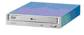
• CD-ROM/DVD DRIVE
Compact disc–read only memory: stores large amounts of data on a CD that can be read by a computer.

Friday, February 8, 2008

Introduction to Computer

The technical term for a PC is micro data processor . That name is no longer in common use. However, it places the PC in the bottom of the computer hierarchy:

  • Supercomputers and Mainframes are the largest computers - million dollar machines, which can occupy more than one room. An example is IBM model 390.
  • Minicomputers are large powerful machines. They typically serve a network of simple terminals. IBM's AS/400 is an example of a minicomputer.
  • Workstations are powerful user machines. They have the power to handle complex engineering applications. They use the UNIX or sometimes the NT operating system. Workstations can be equipped with powerful RISC processors like Digital Alpha or MIPS.

The PC's success

The PC came out in 1981. In less than 20 years, it has totally changed our means of communicating. When the PC was introduced by IBM, it was just one of many different micro data processors. However, the PC caught on. In 5-7 years, it conquered the market. From being an IBM compatible PC, it became the standard.
If we look at early PCs, they are characterized by a number of features. Those were instrumental in creating the PC success.

  • The PC was from the start standardized and had an open architecture.
  • It was well documented and had great possibilities for expansion.
  • It was inexpensive, simple and robust (definitely not advanced).

The PC started as IBM's baby. It was their design, built over an Intel processor (8088) and fitted to Microsoft's simple operating system MS-DOS.

Since the design was well documented, other companies entered the market. They could produce functionable copies (clones) of the central system software (BIOS). The central ISA bus was not patented. Slowly, a myriad of companies developed, manufacturing IBM compatible PCs and components for them.
The Clone was born. A clone is a copy of a machine. A machine, which can do precisely the same as the original (read Big Blue - IBM). Some of the components (for example the hard disk) may be identical to the original. However, the Clone has another name (Compaq, Olivetti, etc.), or it has no name at all. This is the case with "the real clones."


Today, we differentiate between:
· Brand names, PCs from IBM, Compaq, AST, etc. Companies which are so big, so they develop their own hardware components.

· Clones, which are built from standard components. Anyone can make a clone

Components in the central unit - the computer
The motherboard: CPU, RAM, cache, ROM chips with BIOS and start-up programs. Chip sets (controllers). Ports, buses and expansion slots.
Drives: Hard disk(s), floppy drive(s), CD-ROM, etc.
Expansion cards: Graphics card (video adapter), network controller, SCSI controller. Sound card, video and TV card. Internal modem and ISDN card.

Peripherals:
Keyboard and mouse. Joystick Monitor Printer Scanner Loudspeakers External drives External tape station External modem

Key Functions of a PC:

Before looking at specific PC components, it is worth taking a few moments to consider the key functions that are performed by a computer:
Input - Entry of raw data; for example, typing names and addresses on a keyboard or transmitting a picture from a digital camera.
Processing - Manipulation of the raw data to produce useful information, the key purpose of a computer; for example, sorting or indexing the names and addresses or adding effects to the picture.
Output - Transformation of the data into information, perhaps in a non-computerized format; for example, printing mailing labels from a database or displaying the picture in a brochure
Storage - Retention of the data until it is needed; for example, filing names and addresses in a database or archiving the picture in an online library. With a basic understanding of these key functions, the role of each of the components of a PC becomes much clearer

Search

Google